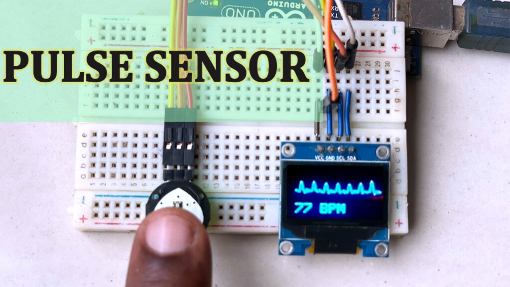
Heart Rate Pulse Sensor Circuit Diagram The Pulse Sensor is a low-power plug-and-play heart-rate sensor that is well designed. The sensors will signal to 16×2 display to show our pulse rate BPM. this sensor is easy to use and operate. Just place your finger on top of the sensor and it will measure the heartbeat changes. Required Material In this tutorial , you will need : Arduino
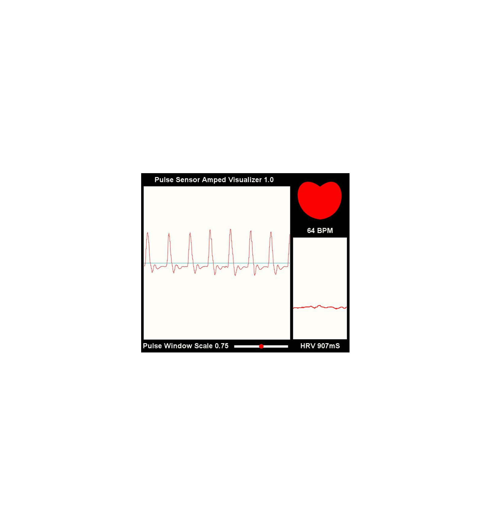
The Pulse Sensor developers have created software to visualize the Pulse Sensor data on your computer. It is written in the Processing programming language. This software displays all of the data that the Arduino receives from the Pulse Sensor. It plots the user's heart rate in real time. A pulse sensor, like any other optical heart-rate sensor, operates by emitting a green light (~550nm) onto the finger and gauging the quantity of reflected light with a photosensor. This method of optical pulse detection is termed a Photoplethysmogram. The vcc pin of the pulse sensor is connected with the 5v, but you can also connect this with 3.3v. the S pin of the pulse sensor is connected with the analog pin A0 and the ground pin of the pulse sensor is connected with the Arduino's ground. Now let's discuss the programming. Download Heart rate Bluetooth App: pulse sensor heartbeat rate app
Monitor Heart Rate using Pulse Sensor and ESP32 Circuit Diagram
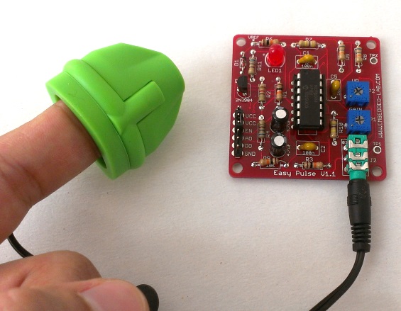
Pulse Sensor Overview. The Pulse Sensor Amped is a plug-and-play heart-rate sensor for Arduino. It can be used by students, artists, athletes, makers, and game & mobile developers who want to easily incorporate live heart-rate data into their projects.It essentially combines a simple optical heart rate sensor with amplification and noise cancellation circuitry making it fast and easy to get
Overview. In this project, we will interface Pulse Sensor with Arduino to Measure Pulse Rate (BPM) or Heart Beat value. The Pulse rate will be displayed on 16×2 LCD Display. A pulse sensor is a hardware device that can be used to measure heart rate in real-time. When paired with an Arduino microcontroller, you can create a simple yet effective heart rate monitor.

Monitor Heart Rate using Pulse Sensor and Arduino Circuit Diagram
The MAX30100 sensor is used as both a heart rate monitor and a pulse oximeter. These features are enabled by the construction of this sensor which consists of two LEDs, a photodetector, optimized optics, and low noise signal processing components. It is easily used with microcontrollers such as Arduino, ESP32, NodeMCU, etc. to build an
